Engine Bay Pictures
This page shows pictures taken when overhauling my engine. To do the task you will need a Haynes manual but these may help with the layout of wiring etc
Crankshaft Pulley Removal | ||
|
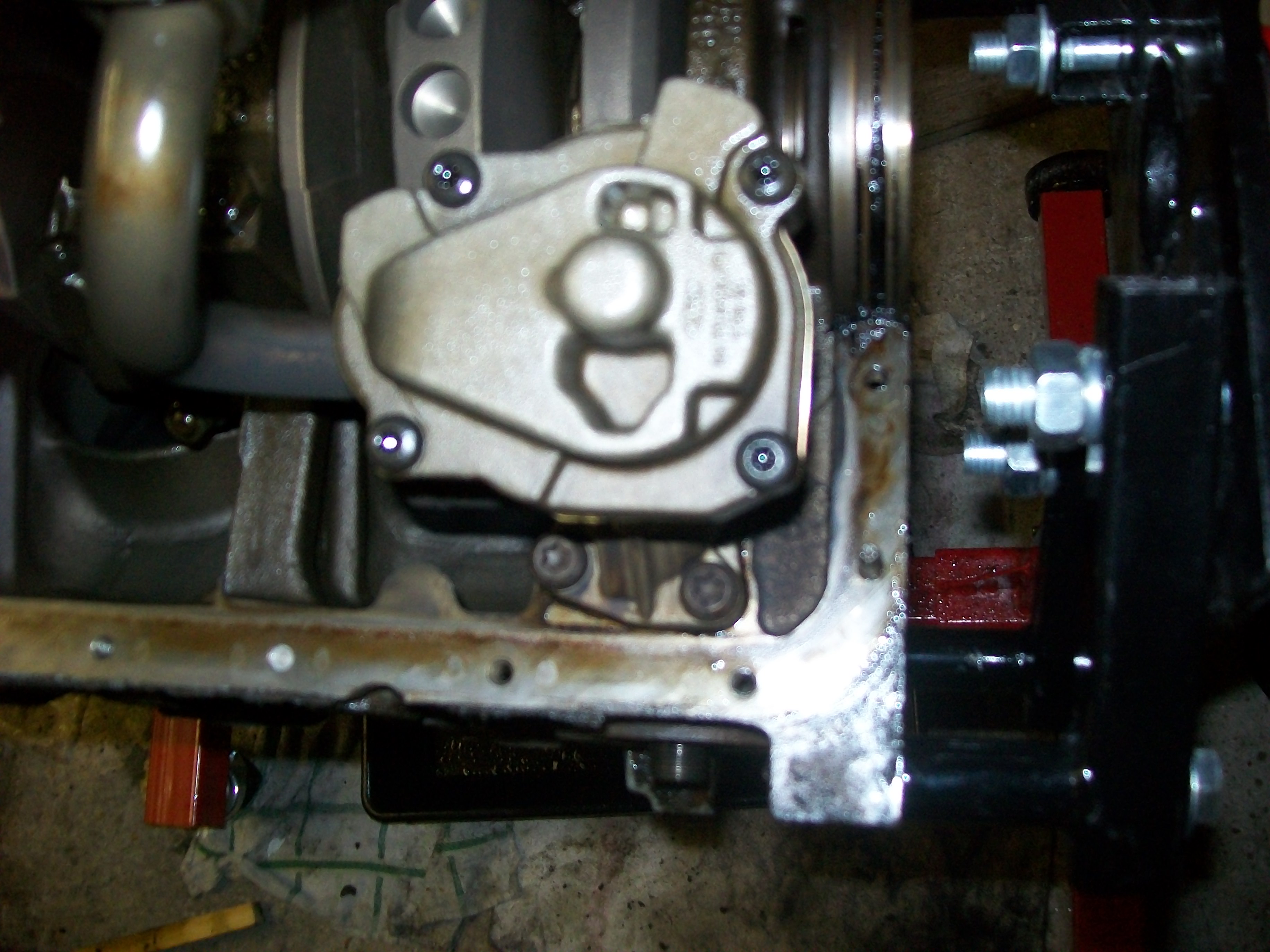
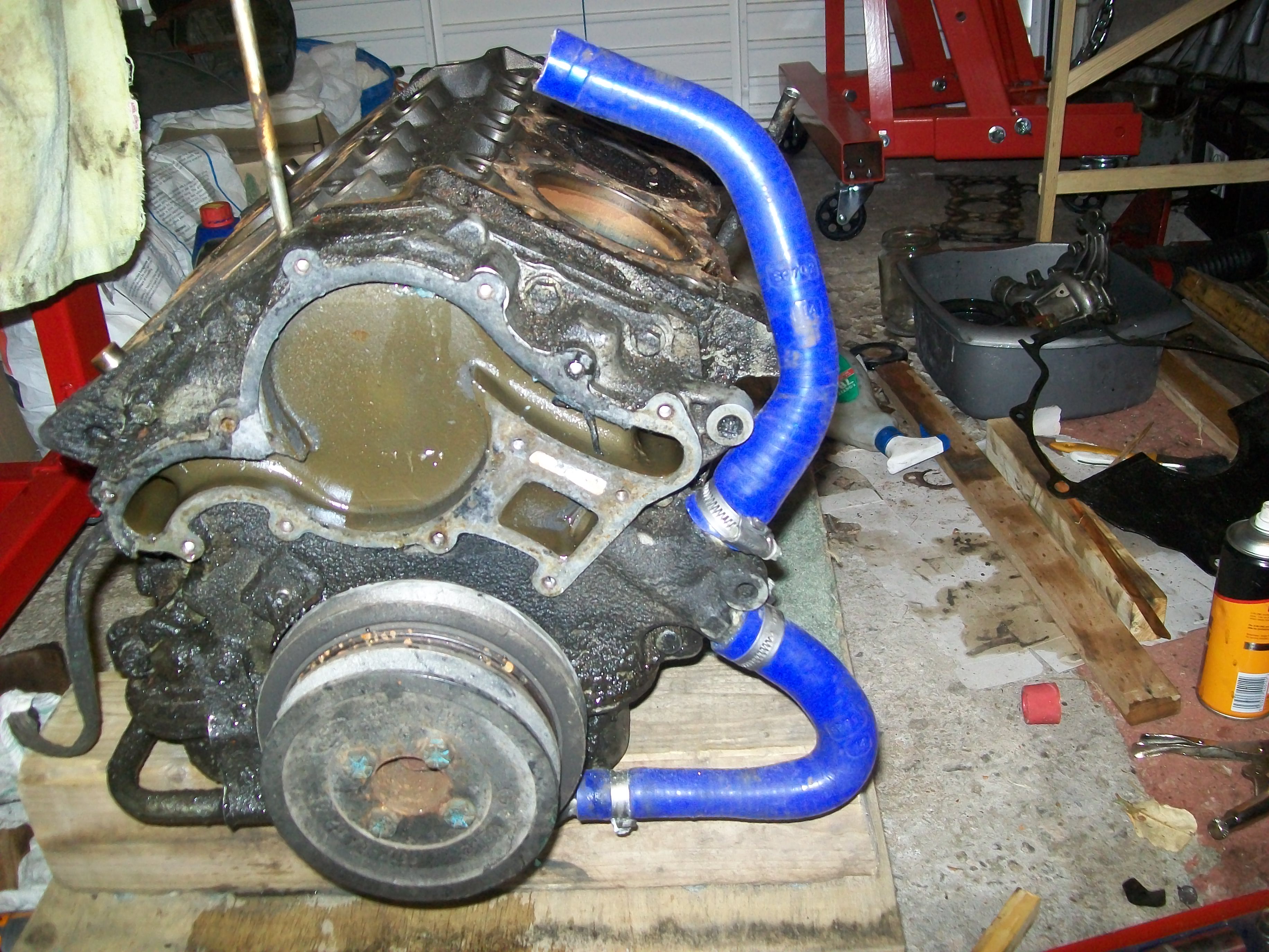
The engine on the bench, heads removed. The clear shape at the top is the water channels for the water pump, which has been removed.
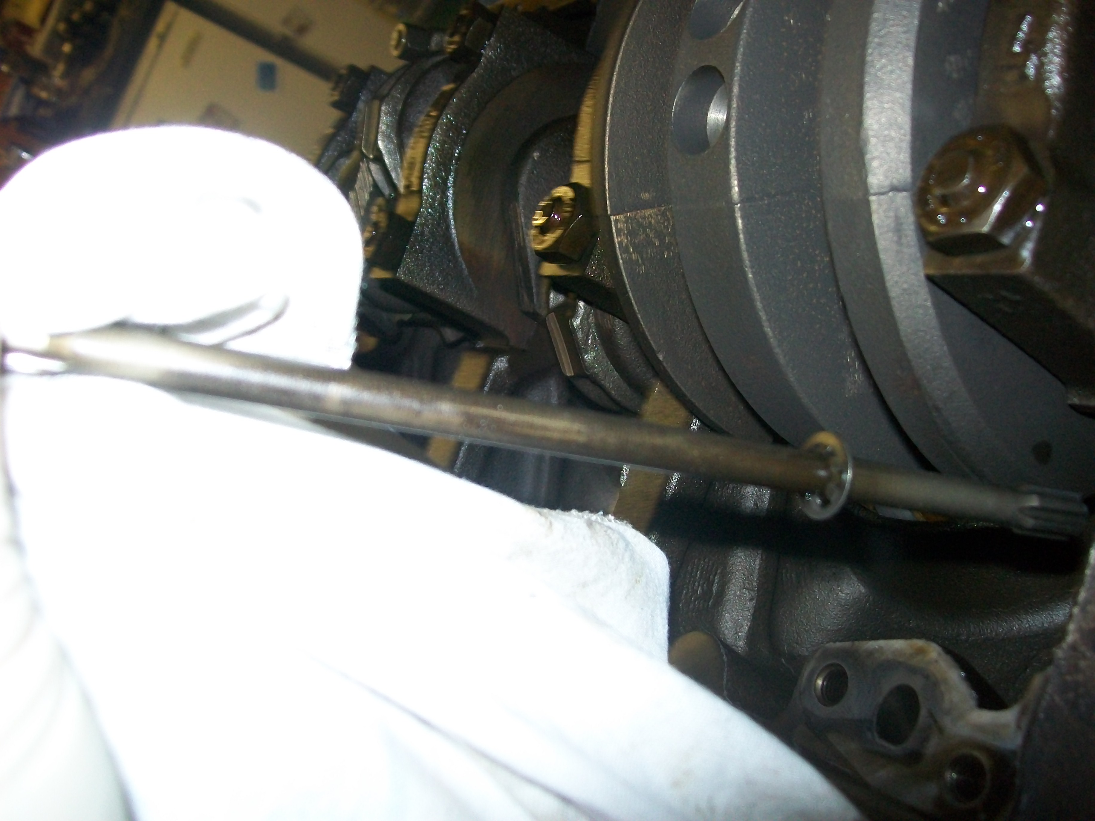
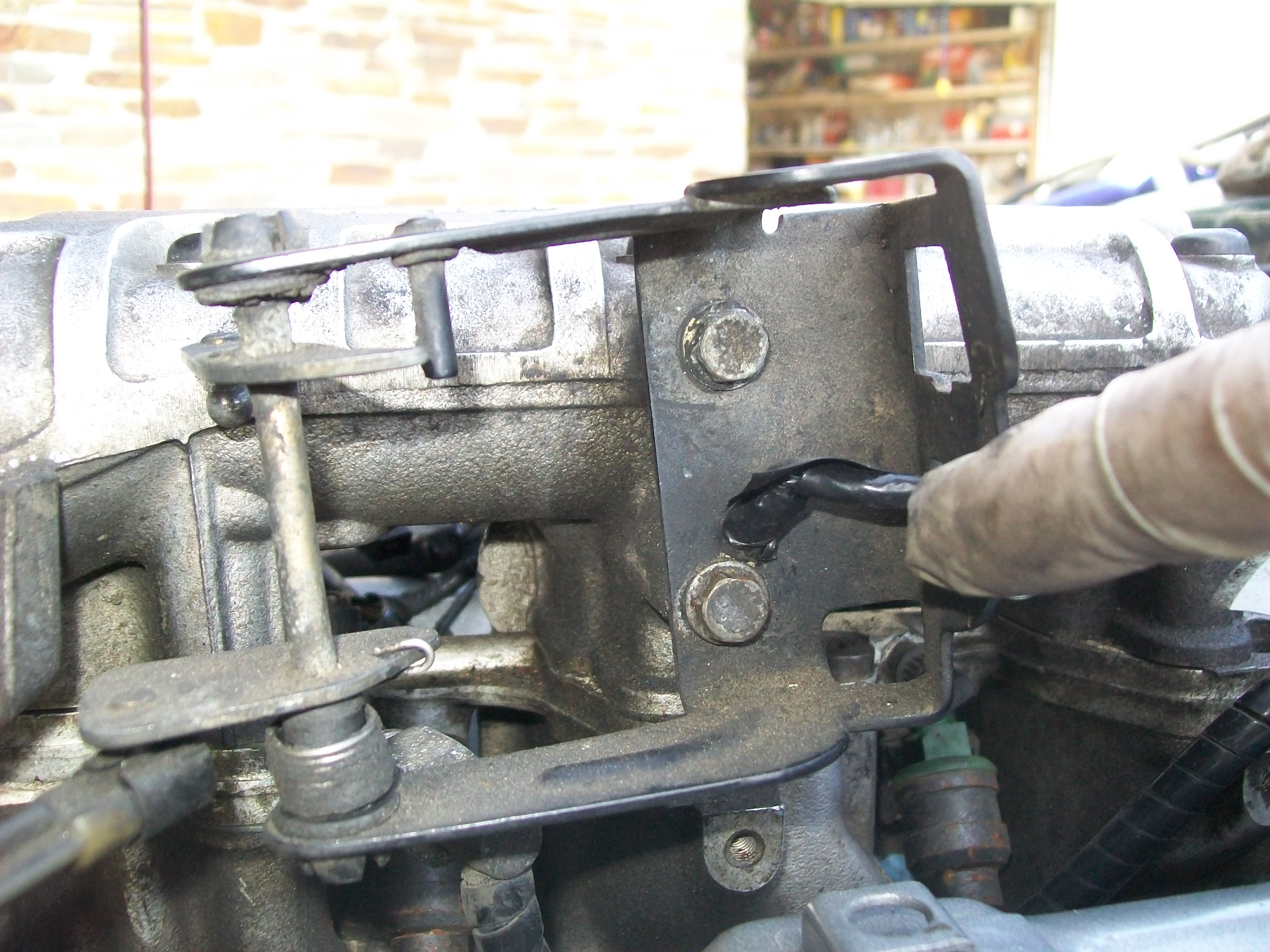
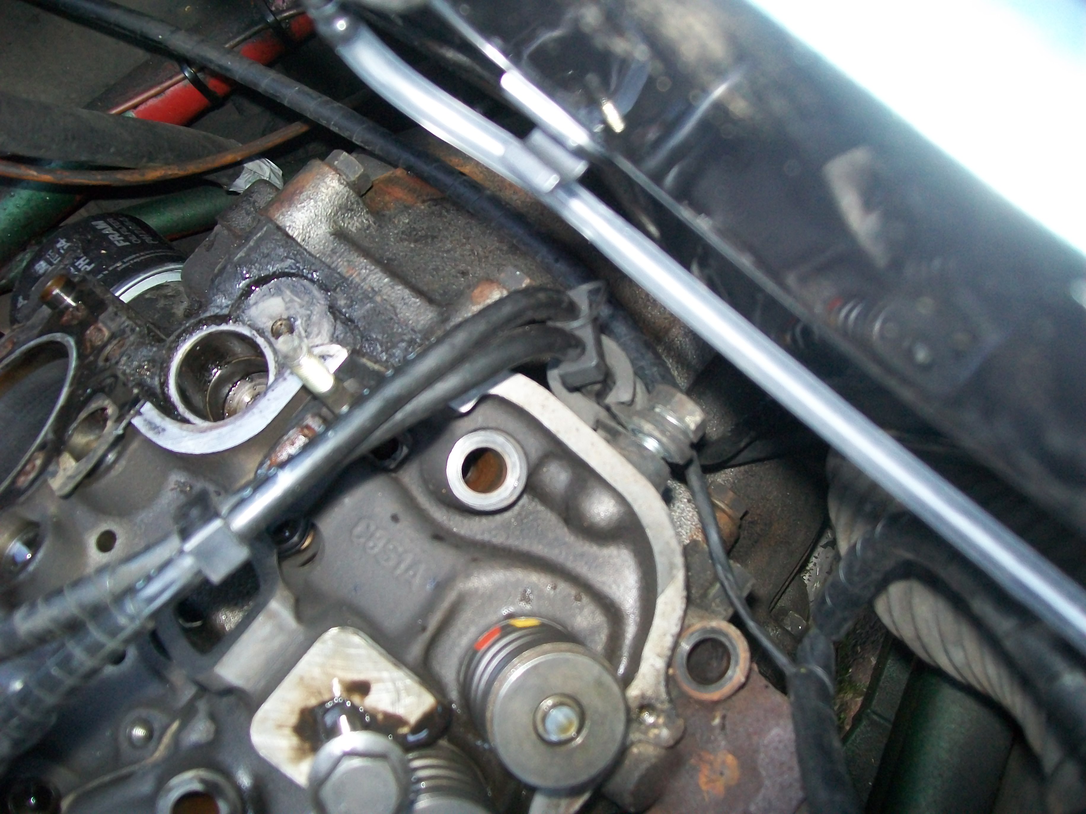
To remove the crankshaft pulley undo the four bolts shown an gently tap the front pulley to remove it. Then undo the crankshaft bolt - this is bleeding tight and will require the flywheel to be held stationary. Once undone insert the bolt slightly and use a cloverleaf style puller with the center on the crankshaft bolt head and the bolts into the pulley bolts where you just removed the four from - these are M10. |
|
View |
Oil Pump | ||
|
The Haynes Manual is not that clear on this so to remove the oil pump you need to undo the torx bolts at the bottom of the picture and then the pump just pulls away reveling the drive shaft in the picture below This is looking at the engine upside down on an engine stand with sump removed. The oil pump is at the flywheel end |
|
View |
Oil Pump Removed | ||
|
Oil pump drive shaft with oil pump removed - you can see the bolt holes for securing the pump in place. | |
View |
Camshaft Timing | ||
|
Back to the timing end of the engine. With the crankshaft pulley and the sump removed you can undo and remove the timing cover to reveal the crank and camshaft sprockets behind and the tensioner. The two indentations must be aligned to get the Camshaft timing correct. Even then it is possible to be a full rotation out when you re-insert the distributor. Well worth checking this if engine doesn't fire on re-assembly. To slacken off the tensioner insert a piece of wire into the small hole on the left of the black plastic (just below and to left of allen headed bolt)and then push in the tensioner runner |
|
View |
Camshaft Timing | ||
View |
Throttle Wiring Electrical Connector | ||
Title says it all | ||
View |
Coil Connections | ||
and again | ||
View |
Engine Layout Drivers Side | ||
and again | ||
View |
Temperature Senders to ECU (near) and Gauge (far) | ||
These are quite well hidden | ||
View |
Fuel Manifold with Plenum Removed | ||
This is the later of the fuel injection rails the earlier one has a different layout and different fitting for the fuel rail back pressure valve which is at the top left of this picture. The connector to the top right is the fuel pipe connection and the schraeder valve for depressurising is clearly visible in the middle to the top of the rail | ||
View |
Fuel Line Bracketing - Rear of Passenger Side Head | ||
As title | ||
View |
Fuel Injector Wiring | ||
and again | ||
View |
Swirl Pot Hose Positions | ||
again | ||
View |
Swirl pot Hoses 2 | ||
again | ||
View |
Swirl Pot Hoses 3 | ||
again | ||
View |